Bending is a fundamental process in the metal fabrication industry, used to create a range of products, from simple household items to complex aerospace components. Different types of bending methods are used depending on the material, the shape of the desired product, and the degree of precision required.
Understanding the different bending methods available can help you select the most appropriate method for your specific application. In this blog, the team at VeriForm Inc. explores some of the most common bending methods used in the industry and the types of bends they produce.
Compression Bending
Compression bending involves the use of hydraulic pressure to deform a section of the pipe and form a bend. This process is commonly used in industrial applications to create bent pipes for various uses, such as in pipelines, plumbing systems, or HVAC systems.
The compression bending process typically involves placing the pipe into a bending machine consisting of a bending die and a counter die. The bending die is designed to deform the pipe into the desired shape, while the counter die supports the pipe and prevents it from collapsing during the bending process.
The machine applies hydraulic pressure to the pipe to compress it against the bending die, causing it to bend gradually to the desired angle. The pressure is then released, and the pipe is removed from the machine.
Compression pipe bending can be used to create bends of various angles and radii, depending on the specific needs of the application. The method is preferred over other bending techniques for thick-walled or heavy pipes, as it can produce high-quality bends with minimal distortion or deformation.
Rotary Draw Bending
Rotary draw bending is used to create precise and consistent bends. In this process, a mandrel is inserted into the tube or pipe to prevent it from collapsing or wrinkling during the bending process. The tube or pipe is then clamped onto a die, and a rotary draw bending machine is used to rotate the die while pulling the tube or pipe around the die to create the desired bend.
The bending process is controlled by a computerized program that ensures the tube or pipe is bent to the correct angle and radius, resulting in accurate and repeatable bends. For this reason, it is a preferred method for metal pipe and tube bending.
Rotary draw bending is commonly used in the automotive, aerospace, and industrial manufacturing industries to create a variety of products, such as exhaust systems, roll cages, and frames.
Roll Bending
Roll bending forms a metal sheet or plate into a curved shape by passing it through a set of three or more rollers. The rollers are arranged in a pyramid shape and rotate around their respective axes, and the metal sheet or plate is passed between them in a series of incremental steps until the desired curvature is achieved.
Roll bending is commonly used in the fabrication of pipes, tubes, and other cylindrical or curved shapes and can be performed using either a pyramid-style machine or a three-roll machine. The process can be used with a variety of materials, including steel, aluminum, and copper, and can produce a range of curves, including tight radii and gradual curves. It is a highly precise and efficient process that can produce consistent results with minimal waste, making it a popular choice for industrial manufacturing applications.
Mandrel Tube Bending
Mandrel tube bending is used to bend pipes or tubes without collapsing or wrinkling the walls of the tube. The process uses a mandrel, which is a solid steel rod or shaft, to support the inside of the tube while it is being bent. This prevents it from collapsing or wrinkling during the bending process.
Before the bending process begins, the mandrel is inserted into the tube. As the tube bends, the mandrel remains stationary and supports the inner radius. This keeps the tube from collapsing or wrinkling on the inside of the bend.
Mandrel tube bending is used in a wide variety of industries, including automotive, aerospace, and construction. It is often used to create complex or custom shapes in tubes or pipes, such as exhaust systems or roll cages. The process can be performed using manual or CNC-controlled tube bending machines.
Press Bending
In press bending, metal sheets are bent using a press brake machine. A flatbed and a top tool move downward to apply force to the metal sheets. After the metal sheet is placed on the flatbed, the top tool is lowered onto it to bend it.
Press bending can be used to create a wide range of shapes, including V-shaped, U-shaped, and channel-shaped bends. It is commonly used in the manufacturing of parts for various industries, including automotive, aerospace, and construction. It can also be used on a variety of materials, including steel, aluminum, and other metals.
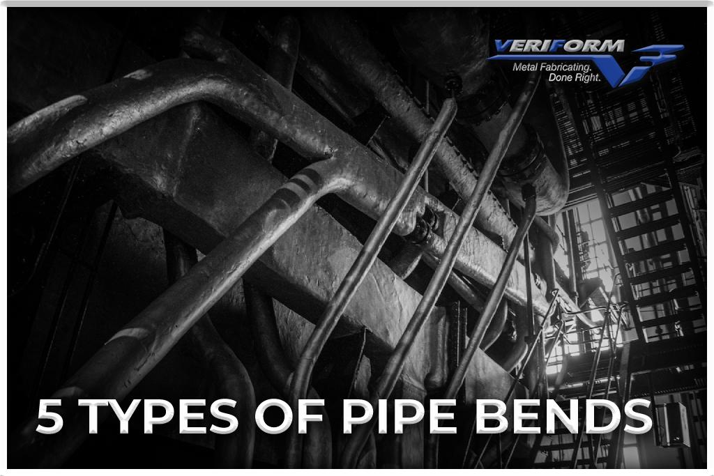
What Are The Different Types of Pipe Bends?
The bending methods described above can be used to shape a wide range of pipes. They include but may not be limited to:
● Long Radius Bend: A long radius bend has a centerline radius that is equal to 1.5 times the pipe diameter. This type of bend is used in low-pressure and low-velocity applications where there is a need for minimum pressure drop.
● Short Radius Bend: A short radius bend has a centerline radius that is equal to the pipe diameter. This type of bend is used in high-pressure and high-velocity applications where there is a need for maximum pressure drop.
● 3D Bend: A 3D bend has a centerline radius that is equal to three times the pipe diameter. This type of bend is used when space is limited, and there is a need for a tight bend radius.
● 5D Bend: A 5D bend has a centerline radius that is equal to five times the pipe diameter. This type of bend is used in applications where there is a need for a larger bend radius.
● 10D Bend: A 10D bend has a centerline radius that is equal to ten times the pipe diameter. This type of bend is used in applications where there is a need for a very large bend radius.
● Mitered Bend: A mitered bend is a custom bend that is fabricated from straight pipe sections. It is used when a specific angle is required that is not available in standard pipe fittings.
The choice of pipe bend type depends on various factors such as the budget, application, space limitations, pressure, and flow rate of the fluid being transported.
VeriForm Inc.: Your Pipe Bending Experts
Pipe bending methods are essential techniques in the manufacturing and construction industries. The choice of a suitable bending method depends on several factors, including the pipe material, wall thickness, diameter, and required bend radius. Overall, understanding the advantages and limitations of each bending method can help you make an informed decision on which one is most appropriate for your application.
At VeriForm Inc., our metal bending services are both complex and diverse. Whether you need parts small enough to fit in your palm or a piece with massive dimensions and tonnage, we can help. To learn more or get a quote for your next project, please visit our website, call 519-653-6000 or contact us online.
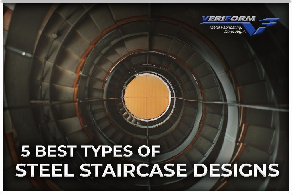
Steel staircases have several advantages. They’re sustainable, low-maintenance, and easy to customize. For these reasons, they’re in demand in all kinds of locations, from homes and offices to factories and industrial facilities.
Choosing the best steel staircase design can be daunting, especially with so many available options. That’s why the experienced team at VeriForm Inc. created this blog to help you explore the five best types of steel stairs and their unique features.
Where Are Steel Staircases Installed?
Steel staircases are versatile and can be installed in a variety of settings, both indoor and outdoor. Here are some of the more common places to encounter them:
Commercial Buildings: Steel staircases are commonly used in commercial buildings such as offices, hospitals, schools, and shopping malls. They provide a durable and long-lasting solution for high-traffic areas and can be designed to comply with safety codes and regulations.
Industrial Facilities: These staircases are also used in industrial facilities such as factories and warehouses. They provide a safe and sturdy access point to mezzanines, platforms, and other elevated areas.
Residential Buildings: Contemporary and industrial-style homes increasingly feature steel staircases. They provide a sleek, minimalist look and can be customized to fit any space.
Outdoor Spaces: Outdoor spaces such as parks, stadiums, and public spaces can also be fitted with steel staircases. They are weather-resistant and can be designed to withstand extreme conditions.
What Are The Best Types of Steel Stairs?
Are you having trouble deciding on a staircase style for your facility? Here are some of the best types of steel stairs in use today.
Straight Steel Staircase
For a steel staircase, this is the most common and straightforward design. It consists of a single flight of straight stairs that goes from one level to another without any turns, making it a perfect option for homes and buildings with limited space. The steps can have closed or open risers, and they can be designed with or without a landing, depending on the height of the space and the desired look and functionality.
One of the benefits of a straight staircase is that it is easy to navigate. Additionally, it can be more cost-effective than other types of staircases, as it requires less complex design and construction. However, straight stairs can take up more floor space than other types of staircases and may not be suitable for small or narrow spaces.
Spiral Steel Staircase
A spiral staircase consists of a central post or column around which the steps wind in a spiral pattern. They are often used in small or narrow spaces where a traditional straight staircase may not fit. They can also serve as a striking architectural feature, adding a touch of elegance and sophistication to any space.
Spiral staircases can have open risers or closed risers and can be designed to turn clockwise or counterclockwise. The steps can be wide or narrow, and the handrail can be made of various materials such as metal or wood.
Floating Steel Staircase
A floating steel staircase is an ultra-modern design that creates the illusion of floating stairs. Unlike traditional staircases, which rely on a visible structural support system such as a stringer or a central beam, floating staircases are designed to be self-supporting, with each step attached to a hidden support structure within the wall or the staircase itself.
These unique steel staircases can be straight, curved, or angled and can feature open risers or closed risers. The steps themselves can be thick or thin and can be designed with various edge profiles. However, they may require a higher level of structural engineering than traditional staircases and may be more expensive to install.
L-Shaped Steel Staircase
An L-shaped staircase changes direction at a landing. It typically consists of two flights of stairs connected by a 90-degree turn. One flight goes up a certain number of steps, and then the other flight begins at a landing and goes in a perpendicular direction. The landing in between the two flights of stairs can be either a small platform or a larger area that allows for a turn and rest. L-shaped steel staircases provide an elegant and practical solution for changing elevations while taking up less floor space than a straight staircase.
U-Shaped Steel Staircase
A U-shaped staircase consists of two parallel flights of stairs connected by a landing at the bottom and/or top, creating a U-shape in plan view. The stairs are typically wider than those in a straight or L-shaped staircase, which allows for a more spacious feel and greater traffic flow. They also provide a continuous handrail, which can improve safety and accessibility. The landing in the middle of the staircase can serve as a natural pause point or gathering spot.
Overall, a U-shaped staircase can be a stunning architectural feature that adds both style and functionality to a space. However, they do require careful planning and installation to ensure proper structural support and safety.
What is the Best Metal for Fabricating Steel Staircases?
There are many factors to consider when choosing the best metal for stairs, including the specific application, design requirements, durability, and maintenance requirements. These are some of the common types of metal used for stairs:
Aluminum: Aluminum is a lightweight and corrosion-resistant metal that is easy to maintain and can be finished with various colours and textures. However, aluminum may not be as strong as steel and may require additional support for heavy traffic.
Steel: Steel is a popular choice for stairs due to its strength, durability, and versatility. It can be shaped and welded to create different designs and can be finished with various coatings to prevent corrosion and wear.
Stainless Steel: Stainless steel is a corrosion-resistant, low-maintenance metal that provides a modern, sleek look. However, stainless steel can be expensive and may require more maintenance to keep its shine.
Bronze: Bronze is a durable, corrosion-resistant metal with a classic, elegant look. It can be shaped and finished to create intricate designs but may require more maintenance to prevent tarnishing.
Ultimately, the best metal for stairs will depend on the project’s specific requirements, including the design, location, and budget. It’s best to consult with a professional to determine the best metal for your particular needs.
VeriForm Inc.: Your Steel Fabricating Experts
A steel staircase can significantly affect how people use and perceive your space. Once you decide on the best design for your needs, your next step should be contacting a steel fabrication company with a reputation for quality results.
At VeriForm Inc., our architectural fabrication services are the result of unique and creative collaborations with engineering and design firms. We work with different types of steel to bring your chosen steel staircase design to life. Learn more or get a quote for your next project by visiting our website, calling 519-653-6000 or contacting us online.
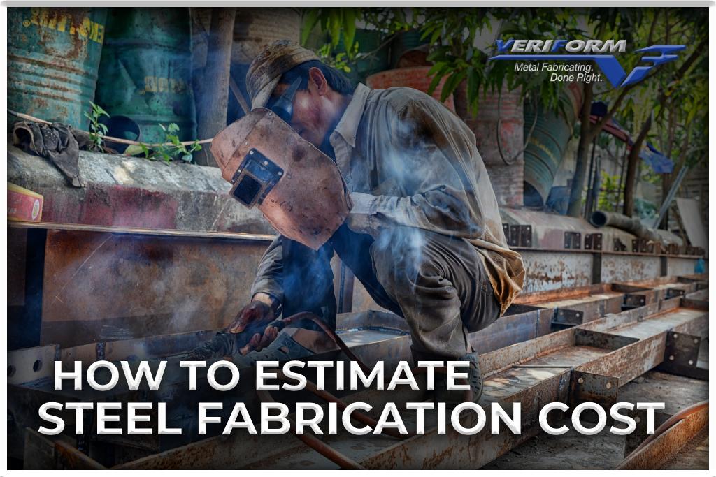
In the metal fabrication industry, knowing how to accurately estimate steel fabrication cost is critical to satisfying customers and protecting your profit margins. While it’s not too difficult to come up with an estimate for time and materials, they are only part of the equation.
Steel fabrication projects come with associated costs – the design, prototyping, finishing processes, etc. To get the most out of your project while keeping clients satisfied, you need to have a cost-saving plan. The following tips, which have been compiled by the experienced team at VeriForm Inc., will help you strengthen your job costing and maximize profits and resources.
Cost Estimation of Steel Products- Getting Started
In today’s competitive markets, it is important to have a clear understanding of cost structure before developing a pricing strategy. The sheet metal production cycle includes bending, forming, punching, welding, and many more phases, each with its own associated costs.
To start, break down the production cycle into more straightforward processes, so you can focus on one process at a time. Then follow the steps below to get an accurate estimate of the costs involved.
Prepare a Raw Material Cost Calculation
You’ll need to estimate the number of raw materials needed to complete a single product associated with the project. Use the following steel fabrication cost calculator to estimate the material cost per product piece:
Raw material cost= volume x density of material x cost of material per kilo
If you’re purchasing steel with a density of 7.4kg/dm3 at $0.8 per kilo and the plate dimensions are 700x300mm with a 1mm thickness, you’re looking at a raw material cost of $1.29. See the calculations below:
(7 x 3 x 0.01) x 7.4 x 0.8 = 1.29
This process must be repeated for each raw material.
Calculate the Machining Cost
At this point, you must know the hourly cost, efficiency, and cycle time (productivity) of the machines being used. To calculate this information, use the formula below:
Machining cost= (hourly cost x cycle time for single piece) / efficiency
If the cycle time is 10 seconds with an 87% efficiency and hourly cost of $77.30, this formula will yield the following information:
(77.30 x 10) / (0.87 x 3600)
Machining Cost = (78.4 x 12) / (0.855 x 3600), which yields a total of $0.24.
To get the total production cost for a single fabricated piece, combine the cost of your raw material with the machining cost. Using the figures above, this would be:
$1.29 + 0.24 = $1.53
These calculations can give you a reasonable idea of your costs during this particular machining aspect of the production cycle.
Calculate Costs For The Different Phases of Production
Now that you have the production cost for one machine, you can apply the same cost calculator for other machines or phases. This way, you’ll get an accurate idea of your steel fabrication costs from the moment production begins until the product is ready for delivery.
Factors That Affect the Cost of Steel Fabrication
In this section, we’ll discuss some of the different factors that may influence the cost of metal fabrication for your project.
Raw Material Costs
Raw materials often fluctuate in price, causing steel fabrication costs to vary. Other factors related to raw material cost include:
Transportation (the closer your facility is to the source, the lower this cost will be)
Metal thickness
Requirement for multiple materials
Supply chain disruption
Plating and Welding Costs
When sheet metal arrives pre-plated, welding is risky because the coating can release zinc oxide when heated. If you go with uncoated steel, you’ll want to coat it after fabrication to make it more corrosion-resistant. This added step increases both cost and lead time.
Work Required
The amount of physical work required to complete the metal fabrication process will dictate the number of workers needed, which affects labour costs. Some applications, such as the use of CAD/CAM software, call for expert skills that typically cost more.
Metal Structure Qualities
The design complexity of the metal structure will affect the cost of fabrication. For example:
A project with fewer bends, cuts, and welds will cost less.
Intricate designs and tight tolerances often require longer manufacturing times and incur higher labour costs.
Tips for Reducing Steel Fabrication Costs
There are ways to reduce steel fabrication costs without impacting the integrity of your project.
Using Standard Metal Sizes and Gauges: Standard sheet sizes are often less expensive than special-length sheets. Selecting material grades based on present market conditions can help minimize costs associated with variable gauges.
Strategic Material Selection: Raw materials affect sheet metal fabrication costs. Use stock sizes whenever possible and choose less expensive materials for prototypes. You can also reduce costs by buying mill-direct.
Lower-Cost Finishing Options: A special finish may require cost estimators to obtain external quotes, adding to the price and lead time. Some standard finishes are less expensive and faster to obtain. Finishes such as chrome plating and powder coating are readily available at a minimal cost.
Contact a Professional Steel Fabricator: A fabrication company capable of handling most of the process on its own can speed up production and deliver products of the highest quality while helping to save costs in the long run. By connecting with a reputable steel fabricator, you can get the products you need at a competitive rate.
VeriForm Inc.: Your Steel Fabricating Experts
One of the factors to consider when designing sheet metal parts is fabrication costs. If you follow the tips discussed above, you can effectively control and even reduce the cost of steel fabrication.
VeriForm Inc. provides customers with cost-effective steel fabrication services calculated to deliver maximum cost savings. Our unique combination of an expert team, quality materials, and efficient machining processes results in superior results at a competitive rate. Learn more or get a quote for your next project by visiting our website, calling 519-653-6000 or contacting us online.
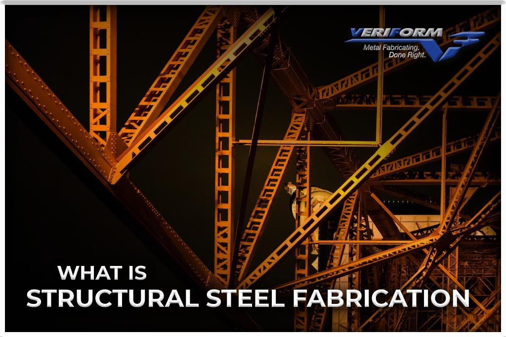
Structural steel fabrication is the process of cutting, bending, and shaping steel components for later use in steel structures like buildings, towers, and bridges. The various steps involved, which include the use of complex fabrication technologies, often call for equal measures of experience, skill, and artistry.
Structural steel fabricating is a specialty skill that requires experience in converting raw materials into products that meet applicable codes and standards. It is widely used in the following industries:
Aerospace
Automotive
Construction
Energy
Manufacturing
Mining
Shipbuilding
At VeriForm Inc, our structural steel fabrication services are provided by highly skilled tradespeople and state-of-the-art equipment. In this article, we’ll explain what structural steel fabrication is, what it’s used for, and how a top-rated Ontario metal fabrication company can help you get quality results.
What is the Most Commonly Used Structural Steel?
Steel’s chemical composition and the treatments it undergoes can affect its hardness and ductility, making different types of steel suitable for specific applications. We’ll discuss the three main types of structural steel below.
Carbon Steel
For structural applications, carbon steel is a popular choice. As a matter of fact, it is the most commonly produced steel in North America. Carbon steel is both strong and ductile (it can bend into any shape without breaking), and it is also relatively easy to manufacture.
This structural steel is an alloy, which means that it’s mixed with other metals or non-metallic materials. The main constituents of carbon steel are iron and carbon, with a few other elements alloyed in very small amounts. It is made in a blast furnace by mixing iron with coke (an industrial fuel made from coal or oil). The steel is cast into a mold after undergoing additional processes such as deoxidation. After that, it can be rolled, cold-formed, or heated to create the exact steel you require.
Since carbon steel is so common, it can be used for a wide variety of purposes, from bridges and buildings to bolts and fasteners. Nonetheless, other forms of steel are also suitable for specific applications.
Tool Steel
Steel alloys become stronger and harder when they are quenched and tempered. The first step is to quench alloy steel. In other words, it is heated up to a critical temperature and then cooled down immediately. (To prevent brittle edges on the steel, this process must be tightly controlled.) Following quenching for extra toughness, the alloy will be tempered. In tempering, the metal is heated once more, but below its critical point. It is then air-cooled.
Alloy steel that has been quenched and tempered can be used for many things, including building bridges and skyscrapers. It is also used for making tools, which is why it is called tool steel.
HSLA Steel
The term HSLA refers to high-strength low-alloy steel. Elements like manganese, copper, nickel, zirconium, or more are added to steel to make it harder. Steel was originally designed for pipelines, but now you can find it in cars, cranes, and even roller coasters. Since HSLA has a good strength-to-weight ratio and can withstand a lot of stress, it is an ideal building material.
This steel also tends to be more corrosion-resistant than other kinds due to the particular elements alloyed into it. It is, however, more difficult to manufacture than carbon steel.
What Happens During Structural Steel Fabrication?
Structural steel fabrication is a multi-step process that starts with cutting and bending and usually progresses to welding and assembly.
Structural Steel Cutting
Fabricators cut structural steel using a variety of methods that include:
Oxygen-Acetylene Flame Cutting: This technique is commonly used for general cutting or edge preparation, such as beveling, coping, or notching.
Plasma Cutting: This mechanically-guided process is often used to cut steel plates up to one inch thick.
Laser Cutting: Like plasma cutting, this process is useful for cutting steel plates.
Water Jet Cutting: This manufacturing process uses high-pressure water jets to cut and shape various types of materials.
Shearing: Performed with mechanical presses, shearing is generally useful for cutting plates and angles.
Structural Steel Bending or Rolling
The next step is to bend or roll the alloy. The process of rolling or bending structural steel involves curving it to a specified radius and arc length. The term bending generally refers to creating a bend with a tighter radius, while rolling describes a bend with a larger radius. Bent and rolled steel are often used in environments that require a curved aesthetic, such as domes, arenas, canopies, and roof trusses.
A steel fabricator can hammer steel manually or with a machine. Whether you should do one or the other depends on how much repetitive bending your project requires. Fabricators are more likely to use machinery if bending structural steel is highly repetitive.
Structural Steel Assembly
Combining the various steel parts is the next step in creating steel structures. Although some structures call for the pieces of steel to be joined using rivets, welding is the most commonly used option. This is because welding can make the steel stronger, preparing it for high-pressure applications like I-beams or columns. Compared to riveting, welding gives structures greater strength and durability.
Cleaning and Painting
The last step of the process is to clean the structure surface of any debris. The surface is prepared for painting by using a variety of cleaning methods, such as surface rusting, blasting, etc. Generally, steel structures are painted with two layers of normal paint and one layer of anti-rust paint, which protects against corrosion caused by environmental factors.
VeriForm Inc.: Your Structural Steel Fabricating Experts
Whether you work in the construction industry or the manufacturing industry, a quality structural steel fabrication process is essential for the best results. VeriForm Inc. provides expert welding services on all your fabrication projects, with any oversized or complex parts being welded on Demmeler Bluco fabrication tables for extra accuracy. If you need help with an upcoming structural steel fabrication project, we’ll be pleased to offer a competitive quote. Learn more by visiting our website, calling 519-653-6000 or contacting us online.
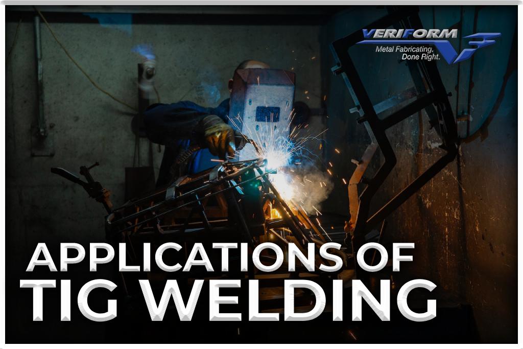
Tungsten Inert Gas (TIG) welding, also known as Gas Tungsten Arc Welding (GTAW) is a form of arc welding that uses a non-consumable tungsten electrode to create the weld. Due to their high performance, strength, and reliability, GTAW welds are commonly used in aerospace and nuclear energy.
In the 1940s, TIG welding skyrocketed in popularity after successfully joining magnesium and aluminum. Today, it’s an appealing replacement for gas and manual metal arc welding because it uses an inert gas shield instead of slag to protect the weld pool.
At VeriForm Inc, TIG welding is one of our core processes due to its corrosion and crack-resistant welds and compatibility with a wide range of metals and fillers. In this article, we look at how TIG welding works and analyze both its advantages and disadvantages in terms of application, operator skill, and efficiency.
TIG Welding: the Process
During TIG welding, a pointed tungsten electrode and the workpiece are joined by an arc in an inert environment of helium or argon. Small intense arcs created by these pointed electrodes are ideal for precision and high-quality welding. Since the electrode is not consumed, welders don’t need to balance the heat input from the arc. Filler metal must be added separately to the weld pool when it is needed.
Advantages of TIG Welding
Make Clean, High-Quality Welds
When appearances matter, you can create clean welds with TIG due to its superior arc and weld puddle control. TIG welding allows you to control the weld puddle’s temperature with a foot pedal, similar to driving a car, giving you precise control over the weld bead. Therefore, TIG welding is ideal for cosmetic welds such as automotive and metal sculpting.
In addition:
With TIG welding, no smoke or fumes are produced, unless the metal being welded contains oil, grease, paint, lead, or zinc. Welding should begin with a clean base metal.
The welding puddle only contains the necessary amount of filler metal, so there is no spatter or sparks when you work with clean metal.
No flux needs to be applied or used because the Argon gas protects the weld puddle from contamination. There is also no slag to obstruct your view of the weld puddle and the finished weld won’t have any slag that needs to be removed between passes.
Only One Shielding Gas is Needed
The versatility of Argon allows you to TIG weld all metals and thicknesses, so you only need one gas in your shop. This simplifies the welding process since you don’t have to work with a variety of gas types.
More Versatile Welding
You can make TIG welds in any position – flat, horizontal, vertical or overhead. This versatility makes it an ideal option for shops that produce items like roll cages or need to carry out welding work in tight or confined locations.
Furthermore, TIG welding can weld a greater variety of metals and alloys than any other method available. You can use this process to weld steel, nickel alloys, bronze, copper, magnesium and even gold. In the case of thin sheet metal, there is no better arc welding process: TIG prevents warping, discolouration, and burn-through by using multiple arc and heat control methods.
Greater Operational Control
TIG welding uses tungsten electrodes to create the electrical arc, which improves control. Unlike stick or MIG welding, where a consumable electrode melts into the weld area, tungsten electrodes heat and melt the filler material that is fed into the weld area by the operator. The level of control can make a difference in the quality of the results.
In addition:
Foot pedals control amperage to the electrode, which is not the case with other welding methods, such as MIG (gas metal arc welding), in which the arc voltage is set at a preset value. A TIG welding setup has variable amperage, which is one of the main differences between it and processes like MIG welding.
TIG welding’s filler material application helps to achieve control. As we mentioned before, TIG welding electrodes are non-consumable, so the operator can better control the amount of filler rod used by separating the filler metal application from the heating step. MIG welding, on the other hand, uses the gun as both an electrode and a filler material.
Disadvantages of TIG Welding
TIG Welding Can Be Difficult
Although TIG welding equipment and materials are relatively affordable, skilled and experienced technicians are needed to perform the process, which can result in higher labour costs. (Even the most experienced welders gradually switch over to TIG welding.)
Welders without experience have a hard time handling heat with the pedal, as an accidental jerk will create small welding craters on the metal surface. Improperly performed inclusions, contaminations, and unbalanced heating can result in warped or defective products, as well as wasted materials.
TIG Takes Longer
TIG welding takes a lot of time. The kind of precision it’s known for is extremely time-consuming compared to other technologies like stick welding. The machines themselves also need to be thoroughly cleaned after each use: since any contamination will corrode the surface being welded, there is no room for error.
Overheating is a Risk
As the temperature is controlled by a pedal, distractions or operational errors can cause overheating. Upon overheating, the metal surface will discolour instantly, making the joint brittle and prone to breaking. You won’t be able to reduce the amperage smoothly if you haven’t developed the pulsing ability. Overheating will result in every time.
VeriForm Inc.: Your Welding and Fabrication Experts
TIG welding is one of many state-of-the-art technologies that have a place in modern metal fabrication shops. At VeriForm Inc, our CWB CSA W47.1 and W59 certified welders deliver expert and outstanding results on your fabrication projects, and all oversized or complex parts are welded on our Demmeler Bluco fabrication tables for extra precision. If you have a routine or complex welding project, we’re here to help. Learn more by visiting our website, calling 519-653-6000 or contacting us online.
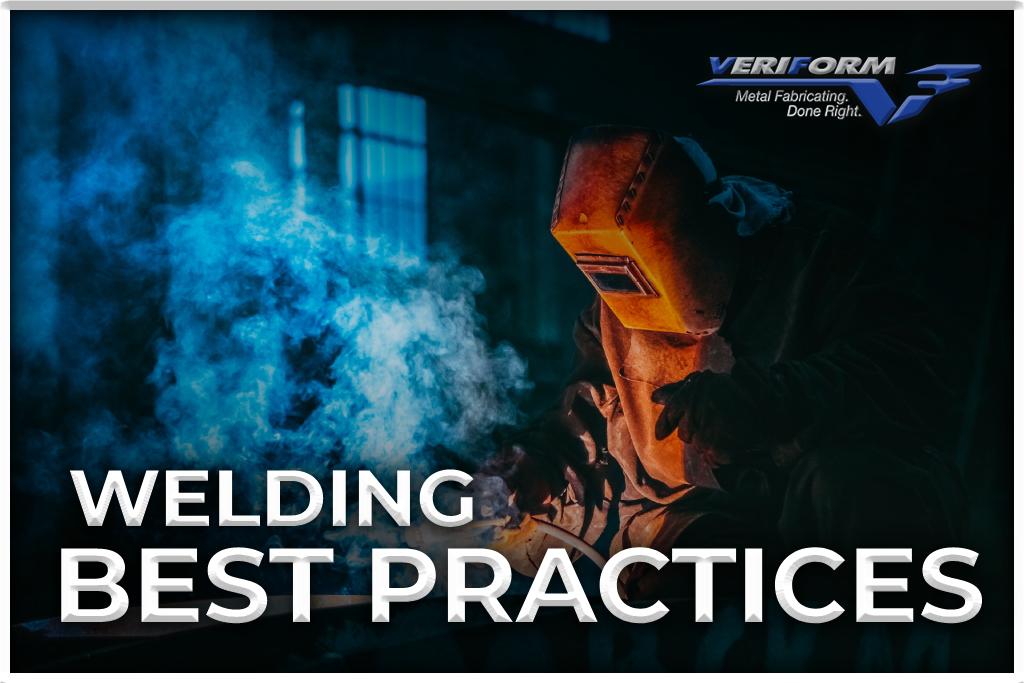
Welding is a process that consists of different technologies and an equally diverse range of materials. The process you use and the metal being worked on will largely dictate the tools and steps involved.
Having said that, there is a set of ‘golden rules’ that can be safely applied to all welding applications. In this article, the experienced fabricators at VeriForm Inc. go over welding best practices that will maintain both efficiency and the quality of your output.
Common Welding Challenges in Fabrication Environments
Although materials with a carbon steel base are often used in welding applications, they aren’t the only ones. Stainless steel, aluminum, and even bronze and titanium are becoming more common in manufacturing and fabricating environments. When you run an enterprise that welds different materials, you’re often looking at investing in more welding equipment as well as adjusting the schedule to accommodate equipment changeover between applications.
Do’s and Don’ts of Welding
Welding solutions designed for different types of materials can help you gain flexibility and efficiency while making high-quality welds. These best practices can help ensure you always have the right equipment on hand and use it to its best advantage.
DO Wear Appropriate Clothing and Safety Gear
Maintaining compliance with safety regulations and personal protective equipment (PPE) requirements is essential. This includes wearing the following during welding operations:
A welding helmet to protect the worker’s face from sparks and the ultraviolet and infrared rays that the arc emits
Clothing that doesn’t have pockets or cuffs that could potentially catch sparks
Respiratory protection to keep the welding fumes at bay
DO Clean the Metal Surface
It’s important to properly prepare the metal before you weld it. This includes removing surface contaminants like dirt, paint, and rust and sanding away any cracks or uneven surfaces. In most cases, a simple going-over with a powered wire brush is sufficient, but be prepared to go further if needed.
Should it be impossible to clean an area before repairing it, don’t use an MIG welder on it. Instead, use a stick welder with a 6011 rod and go slowly so gas bubbles escape from molten welds before these impurities can be trapped.
DON’T Stick to Basic Feeders
Don’t limit yourself to basic options when selecting wire feeders. In welding operations where materials are frequently changed, wire feeders with more advanced technologies can save time and increase productivity.
Dual feeder systems eliminate the need for separate welding cells for different materials. Integrated systems that include the power source and feeder on a single MIG runner cart can save time during setup and make it easy to move the equipment from one cell to the next. Advanced wire feeders also allow welders to save different weld programs, making it easy to retrieve the correct parameters for specific applications.
DO Integrate Pulsed MIG Welding
Welders can produce high-quality welds and reduce rework by choosing a feeder and power source with pulsed MIG capabilities. Compared to CV MIG welding, pulsed welding is much better for aluminum because it provides lower heat input and greater arc control, reducing problems like burning, distortion, and spatter.
There are also advanced pulsed welding processes that help you produce a better-looking weld and bead profile: some versions even compensate for welder inexperience by supporting accurate travel speeds and correct distances between the contact tip and workpiece.
DO Incorporate User-Friendly Welding Technology
With materials like aluminum and stainless steel, it can be more difficult to set the correct welding parameters to support the desired bead profile and penetration. Consider welding technologies that make these parameters easier to attain. For example:
There are welding power sources that assist welders in setting proper parameters. When the welder enters the material type, thickness, and wire size, the machine will establish the parameters necessary to create a quality weld.
When welding aluminum, a power source with a crater and hot start provides better arc starting and stopping capabilities.
DO Choose the Right Filler Materials
It is critical to select the right filler metal for the application and base material. As aluminum and stainless steel come in many types, make sure the filler metal matches the base metal’s mechanical and chemical properties.
DON’T Use the Same Liner and Consumables for Different Materials
Welding steel should not be done with the same liner and consumables that weld aluminum. Cross-contamination or wire feeding issues can result. The liner for carbon steel is usually steel, while the liner for aluminum is plastic or Teflon with tighter tolerances. For the base material, you also need to use the correct feed guides and drive rolls.
DO Use the Appropriate Angle, Arc Spacing, and Speed
The correct angle will depend on the technology you are using. When wire welding, tilt the gun 10° to 15° in the direction you are pushing the weld. Maintain a 20° to 30° lead angle when stick welding.
When it comes to arc spacing, you’ll want to adjust your travel speed so that the arc remains within the leading third of the weld pool. With wire welding, maintain a distance of ⅜ to ½ inch. Stick welding requires a distance of 1/8” between the rod tip and the workpiece.
With travel speed, you’ll know that you’re going too slow when you’re producing convex, wide beads that have shallow penetration while depositing too much metal. If the travel speed is too high, the weld will produce a narrow, highly crowned bead. For most joints, the travel speed is well below 40” per minute.
VeriForm Inc.: Your Welding and Fabrication Experts
When you’re required to weld different materials, how well you adopt welding best practices can make a difference in your success rate. Pulsed MIG and advanced wire feeders allow operators to save time in setup and to produce high-quality welds, so investing in these additional capabilities can have a significant impact on the bottom line.
At VeriForm Inc., our CWB CSA W47.1 and W59 certified welders continually use welding best practices to ensure that we always meet your project specifications. We believe that in order to complete superior-quality welding, we need to use the best equipment and recommended technologies. To learn more about our metal fabrication services, please visit our website, call 519-653-6000 or contact us online.
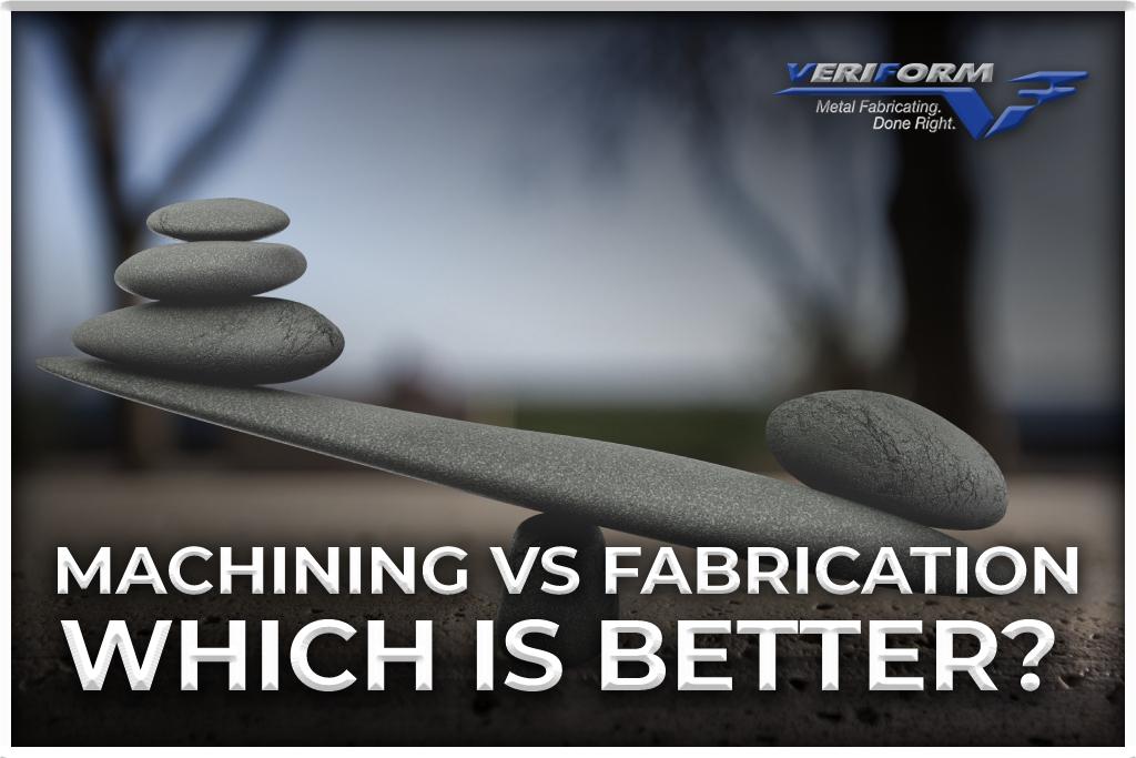
Machining and fabrication are two processes commonly used to create metal parts and components. Although a lot of machine shops and manufacturing facilities employ them to achieve comparable results, they are not the same.
At VeriForm Inc. we use both technologies to deliver client metalworking projects. In this article, we’ll go over the main differences between machining and fabrication and which one you should use for a given application.
What is Machining?
The metal machining process involves removing material from raw metals to make finished products or components. To achieve the desired shape, metal is cut, turned, drilled, or milled using a variety of machines, such as CNC machines. Our new CNC machining centre is long enough to duplicate multiple workstations, ensuring peak productivity and uptime.
Common machining technologies are highlighted in detail below.
CNC Milling
The CNC milling process, which is also known as 3D milling, involves moving the computer-directed tool across the workpiece simultaneously in three axes or more. With these machines, you can contour surfaces and drill holes with extreme precision. As a result, they are indispensable tools in the manufacturing industry.
CNC Drilling
Drilling takes place by rotating either the drill or the workpiece and feeding the drill along its axis into the workpiece. A computer-based drilling system is particularly useful for the mass production of components. With advanced and versatile CNC centres, drilling functions can be performed more quickly and on a repeatable basis.
CNC Countersinking
In countersinking, a V-shaped edge is created near the surface of the hole. It is often used for deburring holes or for making countersunk-head screws sit flush with surfaces. CNC milling commonly uses chamfering endmills to make countersinks.
Threading
Metal threading is a metal processing technique that involves making continuous helical threads on the surface of a workpiece. There are various applications for metal threading, including screws, bolts, and lead screw drives, which require high load capacity and precision in load transformation.
Different threading technologies include:
Thread Cutting: Using tools and dies, thread cutting generates threads on the internal or external surfaces of cylinders and cones. By using a pattern-specific tool, this process removes excess material with each successive pass to achieve desired thread depth.
Thread Milling: During thread milling, the material is removed from the workpiece’s surface with a rotating milling cutter to create threads. The internal threads are carved out by inserting a milling tool into a hole and rotating it in a circular motion. A milling tool is fed to the outer surface of the workpiece to carve out external threads.
Tapping and Threading: In this process, threads are formed through the use of taps and dies. Taps are used to cut or form threads on the internal surface, whereas dies are used to cut threads on the external surface.
Boring
Metal boring cuts a small amount of metal from a workpiece’s inside diameter to increase the accuracy and size of a hole. The process involves rotating either the boring tool or the workpiece and slowly feeding the former along the axis of the latter.
What is Metal Fabrication?
In fabrication, raw materials such as sheet metal, textiles, and plastic are used to create objects and parts. Specifically, the machine fabrication process involves the use of certain techniques to add, remove, cast, join, or form material. The highly trained members of our parts fabrication team use the highest quality precision equipment to cut, bend and assemble complex parts of any size.
Bending
By using a brake, a sheet metal company can bend sheet metal into shapes, and channels at angles up to 120 degrees. The thinner the gauge of sheet metal, the easier it is to bend. The opposite is also possible: sheet metal manufacturers can decamber strip-shaped pieces of sheet metal to remove the horizontal bend.
Cutting
Various pieces of machinery are available for cutting sheet metal, some of which are unique to sheet metal fabrication.
Laser Cutting: Laser cutters use powerful laser beams intensified by lenses or mirrors. They work well on thin and medium gauge sheet metal but may have trouble penetrating harder materials.
Water Jet Cutting: This method of sheet metal fabrication uses a high-pressure stream of water (mixed with an abrasive substance) to cut through the material. Since water jet cutters do not generate heat, they are often used to fabricate parts with low melting points.
Plasma Cutting: By creating an electrical channel of ionized gas, plasma cutters form a jet of hot plasma that can easily penetrate thick-gauge sheet metal. Although not as accurate as laser or water jet cutting machines, they are fast, powerful, and require little setup time.
When the sheet metal is placed between the two machine components, the punch forces itself through the metal to reach the die, creating holes. Punching removes circular pieces of materials, which can either be scrapped or turned into new workpieces- a process known as blanking.
Welding
With welding, heat is applied to a section of metal where it connects to another component, allowing both to be joined together. As the metal melts between the two components, it fuses to form a solid connection. Metals such as stainless steel and aluminum are comparatively easy to weld while others may require a specific welding process, such as arc, electron beam, etc.
Some metal fabricators, including Veriform Inc., also offer powder coating and assembly services for completed components.
As soon as your part is fabricated, it will need machining to knock off the rough edges or maybe a hole will need to be drilled to add a metal component. It is common for something to be machined after it has been fabricated. An example of this would be to add metal objects to a plastic part or remove flash around the edges.
VeriForm Inc.: Your Machining and Fabrication Experts
Machining and fabrication are key technologies when you’re working with sheets of metal. At VeriForm Inc., we have dedicated processes for aluminum, carbon steel, and stainless steel fabrication as well as CNC countersinking, drilling, laser cutting, and tapping. Our in-house personnel efficiencies will prepare and ship your machined and fabricated final products so you’ll have them when needed. To learn more, please visit our website, call 519-653-6000 or contact us online.
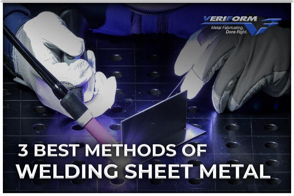
When you’re working with sheet metal, the welding procedure you choose can determine the success of your project. If you don’t use enough heat, the weld penetration will be subpar and you can get brittle joints. Too much heat and you risk burnout.
At VeriForm, Inc. we handle sheet metal using the latest and most advanced versions of proven welding technologies. In this article, we go over the 3 best methods of welding sheet metal, along with recommended applications for each one.
Gas Tungsten Arc Welding
Gas tungsten arc welding (GTAW), or TIG welding, uses tungsten electrodes that cannot be consumed. The tungsten electrode generates an arc that provides heat for welding. Filler material is often used to reinforce and build up welds. As with MIG welding, which will be discussed in the next section, a gas shield protects the pool from contaminants.
Depending on the filler size and how the filler wire is applied, TIG speeds range from 7” to 15” per minute. This method is not normally used on carbon steels due to its comparatively slower speed. However, it may be applied if the size of your MIG gun prevents you from accessing the weld.
Stainless Steel: Because of its clean appearance, TIG is primarily used on stainless steel. It is important to control heat input and speed when TIG welding stainless steel because it is prone to warping when heated unevenly. Unless the adjoining material requires brushing after the weld, there is usually no post-weld cleanup.
Aluminum: For many years, TIG has been the standard process for working with aluminum. For thicker materials, a preheat cycle may be required to ensure complete penetration of the weld. Filler metal is used in the weld puddle, so the speed is generally slower than MIG.
Gas Metal Arc Welding
Gas metal arc welding (GMAW), also known as MIG welding, uses a continuous solid wire electrode fed through a welding gun. When the contact tip is electrically charged, it melts the wire and creates a weld pool between the two components. A shielding gas protects the pool from environmental contaminants that could cause defects. Due to the spatter that is created during welding, MIG is best used for projects in which cosmetics and weld appearance are not important.
GMAW manual weld speeds vary according to the weld size and location, but they are generally around 30″ per minute. Throughput can be increased by using robotic welding. GMAW welding yields the best results on materials like the following:
Stainless Steel: For stainless steel sheet metal, Pulse MIG welding reduces spatter. The electrode does not come into contact with the pool during Pulse MIG welding. An electrode adds molten metal to the pool with each pulse of the current, which alternates between a high and low level.
Carbon Steel: For carbon steel, MIG welding is preferred over TIG welding due to its speed. It can also be used to join parts that do not fit closely together. Typical weld examples include outside corners that require dressing.
Aluminum Sheet Metal: To achieve a TIG-like weld appearance with aluminum, a pulse MIG machine is used with a special assist gas. The surface scale on aluminum must usually be removed before welding to avoid dust and splash marks.
Shielded Metal Arc Welding
Also known as stick welding, shielded metal arc welding (SMAW) uses a consumable electrode with a metal rod at its core. The arc formed between the electrode and the base metal produces the heat required. Disintegrating flux coatings release vapors that act as shielding gases and provide a protective layer of slag. Both prevent atmospheric contamination of the weld area. During the welding process, the metal rod inside the electrode melts, forming a molten pool that creates the weld.
You can control several variables that affect the width and height of the weld bead, the amount of spatter, and the penetration of the weld, making SMAW welding results easier to control. Stick welding is also more cost-effective than other methods, such as TIG. With its portability and versatility, it can be used in any position and with any thickness of sheet metal.
There are some downsides to SMAW welding, such as slag created during the welding process and slower speeds (3” to 6” per minute), but as your proficiency develops these issues are easier to control.
Stainless Steel: Stick welding stainless is easy in flat and horizontal positions, but uphill, it can be challenging. Metal drops seem to fall off faster when the rod gets hot, the arc force seems to drop, and the bead crowns. To avoid these problems, set the amperage at the lower range of the required heat level so that the rod doesn’t get too hot and deposit metal at a more rapid rate.
Carbon Steel: Stick welding is compatible with all grades of carbon steel, from 0.30 to 0.90%. Depending on the grade, it may need preheating and post-welding heat treatment to prevent cracking.
Aluminum: Aluminum is more complicated to stick weld than steel, and the results may not be as aesthetic as you’d like, but it can still be done. Aluminum’s high thermal conductivity and low melting point pose many welding challenges, so you need to apply more heat to the weld pool although the melting point is lower. Getting the right heat requires varying the amperage output on your stick welder, and you’ll need to keep a shorter arc. Be sure to use moisture-sensitive electrodes designed for working with aluminum.
Is It Better to TIG or MIG Weld Sheet Metal?
Sheet metal comes in different varieties, some of which are more suited to one welding method than another. If you’re working with stainless steel, TIG welding will yield the clean visual results you’re looking for. You won’t want to use it on carbon steel, though, because it’s a comparatively slower process.
MIG welding, on the other hand, doesn’t yield attractive results on stainless steel. If you’re working with aluminum, you’ll want to use a MIG machine with a special assist gas. With carbon steel, however, MIG is the recommended approach due to its higher speed.
VeriForm Inc.: Your Sheet Metal Welding Experts
For every project, VeriForm Inc. employs only CWB-certified CSA W47.1 and W59 welders, along with a certified welding engineer. Our on-staff CWB-certified welding supervisors will also supervise your work to ensure the best results for your project. Let us use our experience and in-house efficiencies to prepare and ship your welded sheet metal products, so you have them when you need them. To learn more, please visit our website, call 519-653-6000 or contact us online.
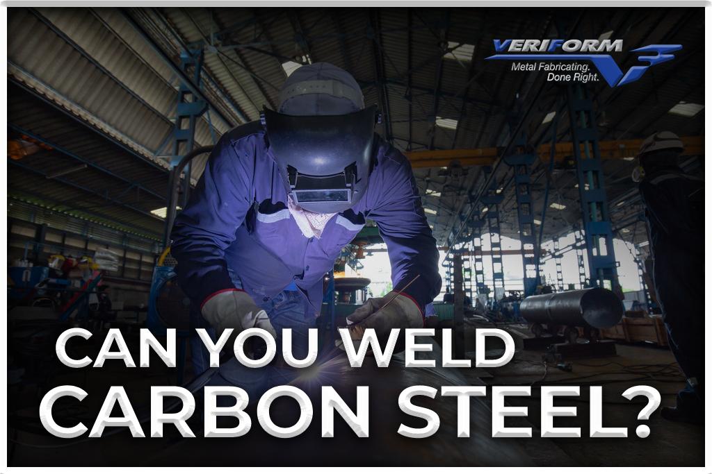
Carbon steel is an iron-carbon alloy with up to 2.1 wt.% carbon. Although carbon steels do not require minimum content of other alloying elements, manganese is often present. The copper, silicon, and manganese content should not surpass 0.6 wt.%, 0.6 wt.%, and 1.65 wt.% respectively. There are three types of carbon steel based on carbon content: low, medium, and high.
At VeriForm, Inc., we are often asked whether carbon steel can be welded. The answer is yes, but depending on the type, you may have to take certain approaches and precautions during the welding process. High carbon steel in particular is crack-sensitive and is prone to significant changes in its mechanical and physical properties after welding, so it is typically considered difficult to weld. However, even high-carbon steels can be welded without problems if you understand the characteristics that make different welding procedures necessary.
Considerations When Welding
Carbon steel is primarily composed of iron, but there are several other elements that can be added (carbon, for instance) that alter its weldability. When welding a project, it is crucial to understand what type of carbon steel is being used. Weld failure can result from ignorance of important variables, such as the added elements or carbon content range in each grade.
Welding carbon steel requires the following knowledge:
Carbon Content: This content ranges from almost 0% by weight to around 2.1%, depending on whether it’s low, medium, or high carbon steel. Low-carbon steel like C1008 is typically the easiest steel to weld at room temperature. Preheating and post-heating are usually required for medium carbon steels such as C1045 while high carbon steel will most likely require more thorough preheating and post-heating processes to avoid cracking. A special welding filler metal may also be required.
Carbon Equivalency: A carbon equivalency formula takes into account other elements in the steel that can affect weldability. The higher the carbon equivalent, the less weldable the carbon steel is. Carbon equivalencies are generally more of a concern with alloy steels.
Cooling Rate: Choosing the right carbon steel to weld also depends on its weld cooling rate. Weld cracking can be exacerbated by high cooling rates. With carbon steels with higher carbon contents and other elements in the carbon equivalency formula, cooling rates should be slowed to prevent weld cracking. Weld cooling rates can be affected by the thickness of the steel as well as ambient temperature.
It is important to note that there are some elements in carbon steel that are not conducive to welding, no matter how much preheat or filler metal is used:
The presence of lead may contribute to solidification cracking, so welding should not be performed on leaded steels.
Sulphur and phosphorus can also cause weld cracking. Carbon steel with a small amount of sulphur or phosphorus can be readily welded; however, steel with more than 0.05% of either could develop solidification cracks. A high level of sulphur and phosphorus makes free machining steels like C1141 unsuitable for welding.
Can You Weld Carbon Steel to Steel?
For many applications, stainless steel is an excellent choice. However, it can be expensive when you want to fabricate large workpieces. A lower-cost carbon steel can therefore be used for non-essential parts and frameworks in larger fabrication projects to help reduce costs.
A strong bond between carbon steel and stainless steel requires special attention to details like heat, filler material, and joint design. Joint preparation, root openings, and preheating are crucial, as are maximum interpass temperatures. In addition:
Stainless steel requires close monitoring of heat input. It is necessary to control the heat and limit the time in the sensitization temperature range. In areas affected by too much heat, corrosion resistance will be reduced.
Different filler metals are required when welding dissimilar metals. In order to prevent an unsatisfactory alloy from forming, stainless electrodes with higher alloy content are used.
For these types of projects, you want to ensure that you work with a skilled and reputable Ontario steel manufacturer.
Which Welding Method is Best for Carbon Steel?
Low and medium-carbon steel is typically the easiest metal to weld. There are different techniques you can choose from.
Arc Welding
One of the most common welding methods for low-carbon steels is an arc or stick welding. During arc welding, a high current passes through a pair of cables attached to the machine’s live and earth terminals. A flux-covered electrode is clamped into a spring-loaded clamp on the live cable. Another clamp secures the earth cable to metal workpieces. Intense heat is produced when the electrode is brought close to the metal. The heat melts metal at the weld point, and the resulting melted flux pool prevents contamination of the weld through oxidation.
Gas Metal Arc Welding
Gas metal arc welding, or MIG, is another common carbon steel welding method. This process works similarly to arc welding, except that the electrode is a continuous wire strand that is fed into the welding point by the welding machine. Weld pools are shielded from contamination by a constant stream of argon gas or argon/helium mixture.
Gas Tungsten Arc Welding
Gas tungsten arc welding, or TIG, is less commonly used, but still a highly effective means of welding carbon steel. Because of its versatility, argon has become the most popular gas used for TIG welding carbon steel and non-alloy steel. It is easy to initiate the welding arc, making it ideal for all types of arc initiation systems.
The versatility of carbon steel makes it suitable for a wide range of applications. VeriForm Inc. provides quality carbon steel parts on time using state-of-the-art equipment and decades of industry experience. Over the years, we have acquired a reputation for product excellence and short lead times.
Our team can assist you throughout the entire process, from the initial design phase to the fabrication of your custom carbon steel part to shipping your finished product, ready for installation. To learn more, please visit our website, call 519-653-6000 or contact us online.
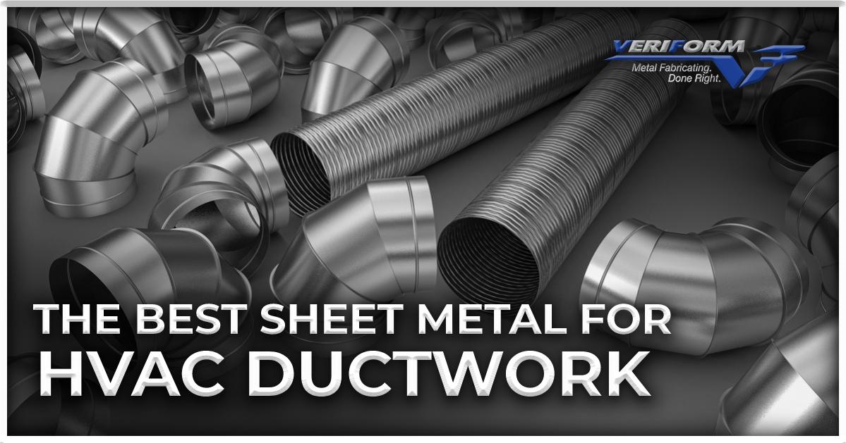
Ductwork fabrication is the process of fabricating customized parts for a building’s HVAC system. Due to their individual designs, homes and commercial buildings all have their own unique heating, cooling, and ventilation needs, which are accommodated by ductwork made from certain types of specialty metal. This blog examines how these ducts are made, what kind of sheet metal is used, and how VeriForm Inc. can produce the results you need.
How are Sheet Metal Ducts Made?
Duct fabrication sheet metal can be fabricated into a variety of shapes, including but not limited to:
Straight oval pipes
Straight round pipes
X, Y and Z connector pieces
90-degree elbows
Half sheet rectangular pipes
Fabrication of sheet metal ductwork involves cutting and forming. With cutting, shears and high-definition plasma equipment are used, while in forming, brakes and presses apply force to shape the material. With this equipment, precise cuts and bends can be created to create specific shapes and position ductwork around obstacles.
One of the most common solutions is rectangular metal ducts, which are formed by combining two bent pieces of sheeting. First, the flat pieces of metal need to be cut to the desired size using a plasma cutter or cutting machine. The sharp edges are then folded inward by another machine. The sheet is then shaped into an L or tube. Rectangular ducting is usually made to standard sizes, but custom sizes can also be created.
Another common option, round metal ductwork, is made using a different process. To begin the process, sheet metal is placed into a coiling machine. To make the pipe airtight, the machine fuses the edges together. Next, the pipe is cut to the desired length.
What Sheet Metals are Used for Ductwork?
Aluminum and galvanized mild steel are the two most common types of HVAC sheet metal.
Galvanized Mild Steel
Galvanized mild steel is highly pliable and can be formed into nearly any shape. This makes it an especially useful HVAC sheet metal for systems with unusual designs or installation requirements. A zinc coating protects the material from deterioration due to corrosion and rust. This ensures the longest possible lifespan in a ductwork system.
Suitable for industrial, commercial, and residential applications, galvanized mild steel can be easily cut, formed, and fabricated. Once fabrication is complete, the ductwork is wrapped in an insulating material to enhance performance and provide sufficient protection against air loss, thereby reducing energy costs. In addition to creating better airflow, galvanized steel sheet metal duct fabrication prevents mold and fungus growth.
Aluminum
The versatility of aluminum makes an ideal duct fabrication sheet metal, since it can be formed into sheets easily. Compared to traditional steel, aluminum is lightweight, making installation much easier, and extremely corrosion-resistant, which is why it is often used in outdoor applications. A typical aluminum sheet comes with pre-insulated panels, and sections are attached at the seams using aluminum tape and glue.
VeriForm Inc.: Sheet Metal Fabricators for HVAC Systems
At VeriForm Inc., we have a full-range metal fabrication service that can customize your sheet metal ductwork to fit your unique application. Our expertise in shaping, rolling, and cutting duct fabrication sheet metal allows us to deliver high-quality products with short lead times.
In addition to these capabilities and custom ductwork fabrication, VeriForm Inc. also offers bulk duct fabrication, which allows us to supply large quantities of sheet metal ductwork right when you need it and at highly competitive prices. To learn more, please visit our website, call 519-653-6000 or contact us online.


 Ductwork fabrication is the process of fabricating customized parts for a building’s HVAC system. Due to their individual designs, homes and commercial buildings all have their own unique heating, cooling, and ventilation needs, which are accommodated by ductwork made from certain types of specialty metal. This blog examines how these ducts are made, what kind of sheet metal is used, and how VeriForm Inc. can produce the results you need.